Abakus Display
- Date:
2017-08-18
Intro
The Abakus Display is very similar to a binary display.
Each digit is represented by 5 LEDs: 4 of them represent a value of 1, the remaining LED represents a value of 5. The 5 LED should have a recognizable position in the display, or a different color. Or not — for advanced geekness. I chose yellow LEDs for a value of 1 and red LEDs for a value of 5.
If no LED is lit up, the overall value of the represented digit is 0. If all LEDs are lit up, the overall value is 1*5 + 4*1 = 9. We can thus represent digits ranging from 0 to 9, just convenient for a decimal display.
I have not seen such a display elsewhere, but I would be very surprised, should I be the first one to do that.
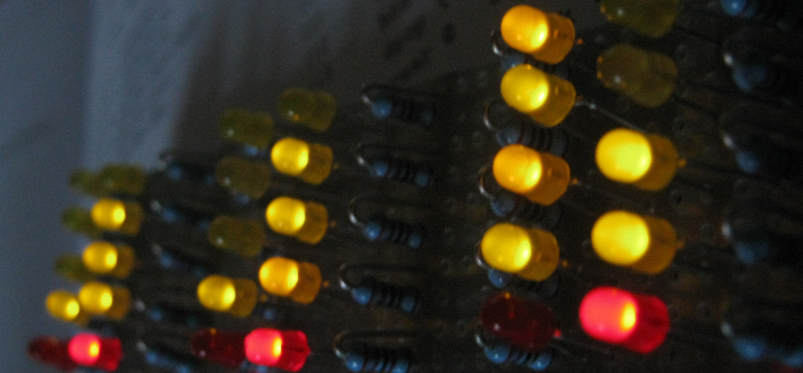
Abakus Display: The image shows six columns of LEDs. Each column represents a digit. The red LED counts 5, the four yellow LEDs count 1 each. So the displayed time is 18:18:47 h.

Schematic: The LEDs of the abakus display are connected to a
shift register. Only one digit is shown, the others are chained as
identical units. The LEDs are connected from +5 V power to the
output pins. So the shift register really sinks the current through
the LED. An output level of 0 or low will light up the LED.
Code Details
The code has two parts
a lookup table to translate a digit (say 7) into the correct bit pattern representing the digit (
$38. see below).two words equivalent to
emitandtype, which are used to acutally display a value.
Lookup Table
The bit pattern representing a digit is determined by the connections
between specific LEDs and the corresponding output pin of the shift
register. For routing reasons, the LED representing the 5 is on output
pin 3: 0000_1000 or 04 is the bit pattern to represent 5. The
LEDs representing values of 1 are connected to output pins 4 to 7.
This corresponds to bit pattern 10, 20, 40, and 80.
The complete table is then
create AbakusDigits
$00 invert , \ 0
$10 invert , \ 1
$30 invert , \ 2
$70 invert , \ 3
$F0 invert , \ 4
$08 invert , \ 5
$18 invert , \ 6
$38 invert , \ 7
$78 invert , \ 8
$F8 invert , \ 9
The values in this table must be adjusted according to the exact
hardware layout.
Please note the invert command. This is another hardware specific
twist: It is quite common to connect the LEDs from high (+5V, say) at
their anode, to low at the shift register output pin. The LED will
then light up, if the output pin is set to 0, i.e. low. The LED will
remain dark, if the output pin is set to 1. So in order to display a
value of 1, i.e. to light up the corresponding LED, we actually need
to write a 0 to that output pin.
emit / type
emit.abakus and type.abakus transfer 1 or n bytes through the
shift registers and assert a latch pulse at last.
\ transfer n digits
: type.abakus ( xn-1 .. x0 n -- )
  0 ?do
    dup 0 #10 within if
    else
      drop 0                            \ map invalid to 0
    then
    AbakusDigits + @i  byte>sr
  loop
  sr_latch low sr_latch high
;
\ transfer 1 digit from lookup table
: emit.abakus ( n -- )
  1 type.abakus
;
Note that type.abakus is not building upon emit.abakus because
asserting the latch needs to be done after the last transfer only.
Otherwise all intermediate states of the shift register chain would
become visible — who wants flickering LEDs?
Also note that type.abakus is verifying that the value on the
stack does not exceed its allowed range (0 .. 9). Invalid arguments
are silently replaced by zeros. This function is kind of hardware
specific and cannot be replaced by a general n>sr, because it
refers to AbakusDigits explicitly.
Putting it all together
All we need to do is to put the desired digits onto the stack and send them out: The first ones that go on the stack are hour-tens and hour-ones, the first ones that are transferred are second-ones and second-tens.
#include shiftregister.fs
#include abakus.fs

: clock.display.abakus.time   ( -- )
  hour @  #10 /mod swap
  min  @  #10 /mod swap
  sec  @  #10 /mod swap
  6 type.abakus
;

: job.sec  ...
  clock.display.abakus.time
;

: init  ...
  +sr
;
The Code
 1\ 2015-10-21 abakus_1.fs
 2\
 3\ Written in 2017 by Erich Wälde <erich.waelde@forth-ev.de>
 4\
 5\ To the extent possible under law, the author(s) have dedicated
 6\ all copyright and related and neighboring rights to this software
 7\ to the public domain worldwide. This software is distributed
 8\ without any warranty.
 9\
10\ You should have received a copy of the CC0 Public Domain
11\ Dedication along with this software. If not, see
12\ <http://creativecommons.org/publicdomain/zero/1.0/>.
13\
14\ #require shiftregister.fs
15
16\ we need a lookup table in sr.emit to map
17\ values (5) to led pattern ($08)
18create AbakusDigits
19$00  invert , \ 0
20$10  invert , \ 1
21$30  invert , \ 2
22$70  invert , \ 3
23$F0  invert , \ 4
24$08  invert , \ 5
25$18  invert , \ 6
26$38  invert , \ 7
27$78  invert , \ 8
28$F8  invert , \ 9
29
30\ transfer n digits
31: type.abakus ( xn-1 .. x0 n -- )
32  0 ?do
33    dup 0 #10 within if
34    else
35      drop 0 \ map invalid to zero?
36    then
37    AbakusDigits + @i   byte>sr
38  loop
39  sr_latch low sr_latch high
40;
41\ transfer 1 digit from lookup table
42: emit.abakus ( n -- )
43  1 type.abakus
44;